Lateral Load Resisting System
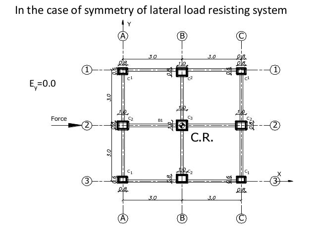
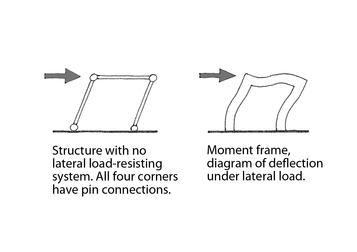
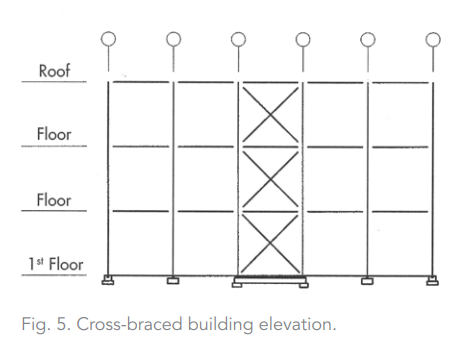
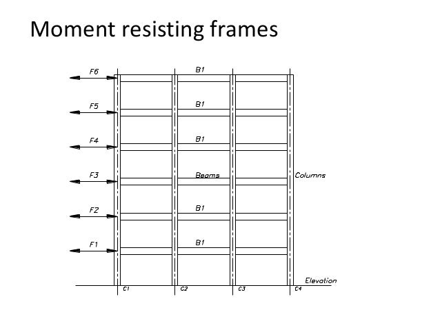
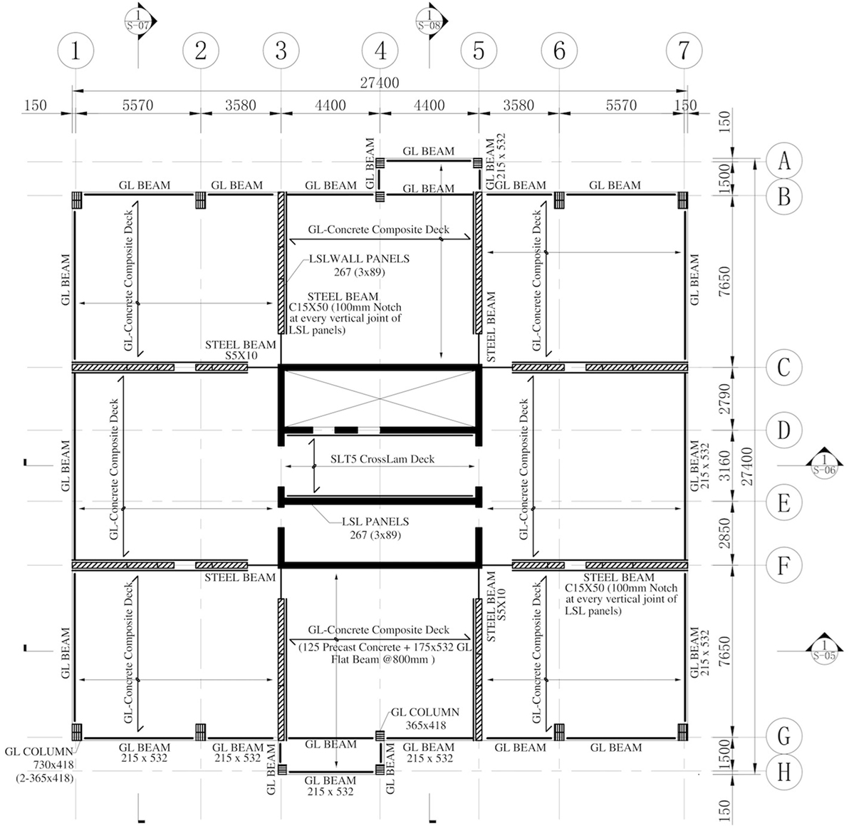
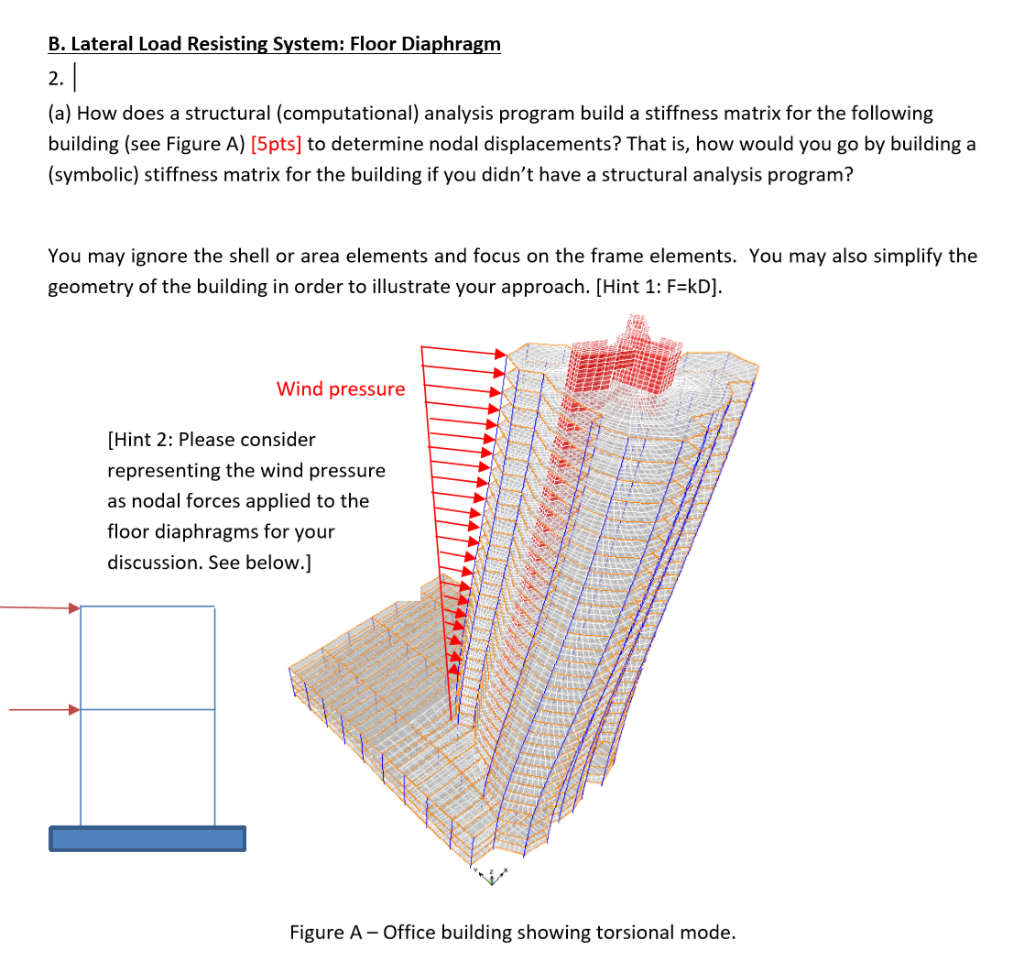
Lateral load resisting system. Because the lateral load resisting systems are symmetric in X and Y directions the center of rigidity is located in the center of the two systems. In most structures the configuration is a secondary consideration determined after the location of the main gravity load-carrying members is set. Lateral Force-Resisting Systems - braced frame shear wall and moment-resisting frame.
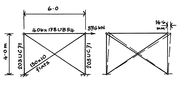
- Transfer axes system to the center of rigidity. LATERAL LOAD RESISTING SYSTEMS AND CONNECTIONS WORKSHEET BACKGROUND All loads eg vertical loads lateral loads impact loads etc on a building or structure must be provided with a continuous path to the foundation. Bracing is generally regarded as an exclusive steel system but nowadays steel bracings are also used in reinforced concrete frames.
The lateral load resisting system consists of 12-inch thick reinforced concrete walls with compressive strength f equal to 6500 psi. Outrig-ger diagrid and diagonal strut with masonry infill are considered as the lat-eral load resisting systems in this study. Swing StoryLateral Force Resisting System Connected with Dampers.
Lateral load resisting systems and also compares the virtual system with the conventional outrigger system. Not only must the individual structural elements andor structural systems resist and. If playback doesnt begin shortly try.
Systems are highly efficient in resisting lateral loads. Calculate the locations of the center of rigidity and center of mass and clearly show them on a neatly drawn sketch. Load path is available to transfer the load into the lateral load resisting system.
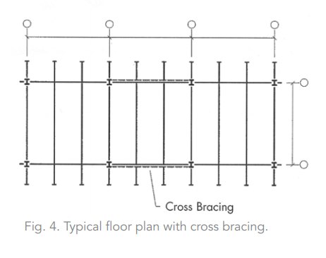
Under most conditions a single brace system is adequate. The diaphragm is a 6-inch thick post-tensioned concrete slab. Of the lateral load resisting system which is the difference between the code prescribed calculated capacity of the system and the load at which the system is expected to realistically begin to yield.
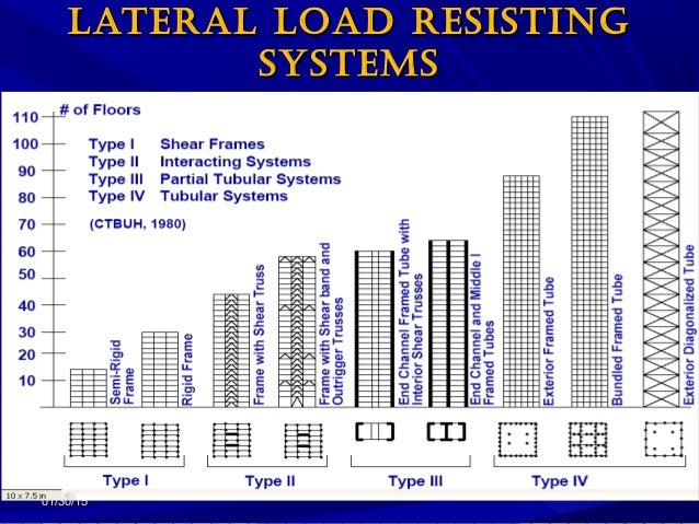
The Wind and Seismic loads are the most common loads that shear walls should carry. The lateral load effect is more prominent in tall buildings.
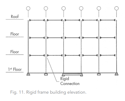
The frame is a group of beams and columns connected with each other by rigid joints and the frames bend in accordance with shear mode whereas the deflection of the shear walls is by a bending mode like the cantilever walls.
LATERAL LOAD RESISTING SYSTEMS AND CONNECTIONS WORKSHEET BACKGROUND All loads eg vertical loads lateral loads impact loads etc on a building or structure must be provided with a continuous path to the foundation. All the buildings constructed need to have lateral load resisting systems. In this paper different lateral load resisting systems to resist seismic loads in high-rise structures has been studied individually. In the case of Cross Laminate Timber both in Canada and the US the FEMA procedure is under way but has yet to be completed. 2-Find the Centre of Rigidity. However an x-bracing system can be used to reduce the buckling length of the compression. The selection of the lateral load resisting system LLRS for s specific building is clearly a design decision of fundamental importance yet there is no system that is best for all buildings. The diaphragm is a 6-inch thick post-tensioned concrete slab. Under most conditions a single brace system is adequate.
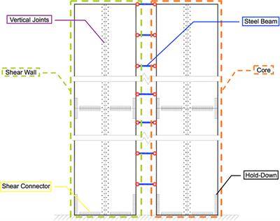
Shear walls are inherently stiff elements and are therefore extremely effective at. The Wind and Seismic loads are the most common loads that shear walls should carry. Not only must the individual structural elements andor structural systems resist and. Of civil Engineering Gogte Institute of Technology Belgavi Karnataka India 2Asst. Because the lateral load resisting systems are symmetric in X and Y directions the center of rigidity is located in the center of the two systems. Bracing is generally regarded as an exclusive steel system but nowadays steel bracings are also used in reinforced concrete frames. Shear walls are inherently stiff elements and are therefore extremely effective at.























Post a Comment for "Lateral Load Resisting System"